This section is supposed to give all of you, that never before had something to do with electronics, an idea of
how to build the connections. (I am included of course)
Welding, wiring and making the right connections may appear at the beginning as a task that is allmost impossible
to achieve without help, if you have never done these things before.
Exactly this point and of course the programming of the EPIC were (at least for me) something that made me doubt if I
should get into using EPIC or not. Thanks to the help from Martin "Pegasus" I made my mind up and right now I can
assure, that EVERYBODY can do it. - Technics are made by men for men and not by the gods for the gods. Therefore of
course it might take some practice (don't worry, not too much ;) ) but after a while you will be able to build up
good working and good looking connections.
Of course you need some tools to do so, but they are cheap and very usefull in any household.
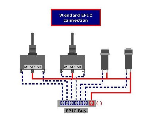
A standard connection needed when using EPIC is shown in the drawing below. Please remember, that when using EPIC
the negative current is interrupted, while the positive is delivered to each switch separately.
The negative current wire is red on the drawing and I used the same colour when building the connections, while
the positive wires are gray. Sometimes I also used black for the positive, when I did not use flat cables.
Also I used blue for the positive current for lights and green for the negative current cables. These 4 colours
allow a simple identification of the wiring, specially when doing some maintenance works later on in your sim.
NOTE: In the diagram I have drawn the positive blue, but as mentioned, they should be gray or black, but
to keep on with the design of the HP I felt I could use it this time ;)
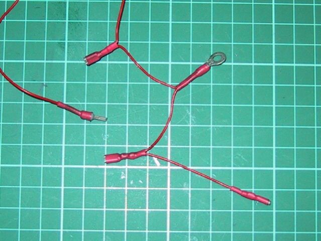
As the wires that are used are very thin, it is not seldom that after doing all the welding and connections they
tend to brake at the place where the connectors are located. It is nasty to have a panel allready installed in your
sim and when you start the simulation no action on one or more switches is achieved.
In the following pictures I am showing how to avoid this cable-breaking. By the way, the appearence improves also and
the connections start to look more professional.
|
Required Tools & Materials
|
Tools (and extras ?)
|
Req. Materials I
|
Req. Materials II
|
|
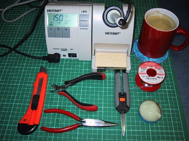
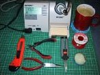
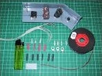
The required tools are shown in the first picture. The hot coffee is not exactly a tool, but for me it is a must when
working on my project ;)
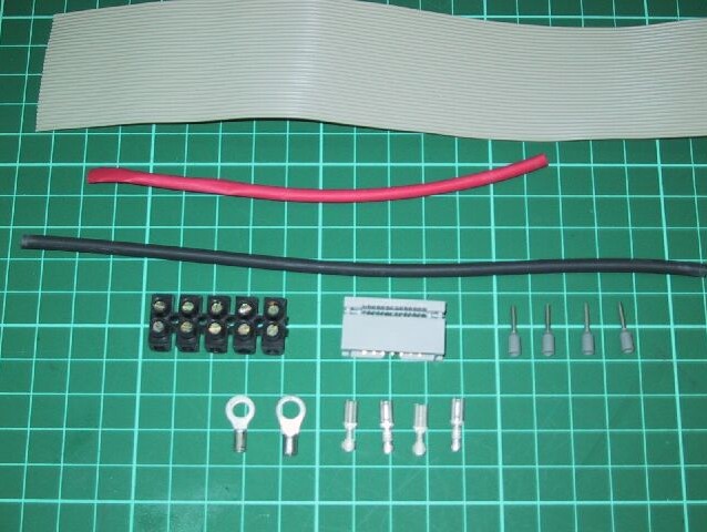
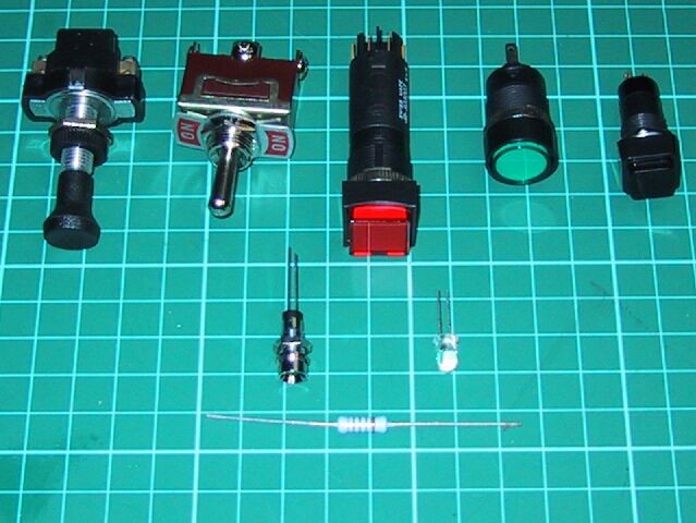
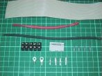
On the next two pictures you can see different kinds of connectors to be used. All of them can be found in normal
hadrware-stores. The flat cable and connector is normally available at any computer store. The shrinking tubes can
be found in different colours and diameters. I use the according colour to the wire-colour I am using. The smallest
tube-caliber will fit perfectly.
The lighter is used to shrink the tubes once you have made all connections. This will give you a neat cover of the
connector, it will improve the stability of the connection itself and give a clean neat look to your work.
|
Switches, Buttons, Resistors & LEDs
|
|
|
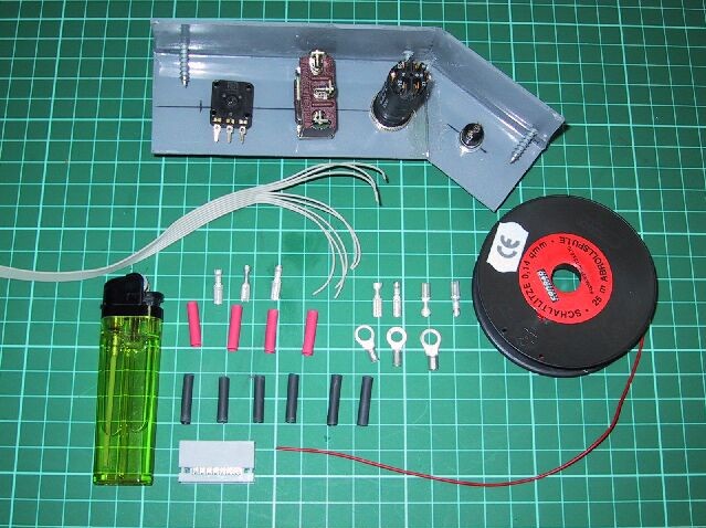
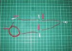
All kinds of devices can bee hooked up using these connectors. When the attaching of the wire to the device is secured
with a screw (for example rthe pull-push switch shown at the top left) a round pin connector is the ideal solution.(Req.
Materials,- at the mid right side) They are simple to connect, as you just have to place the stripped wire through
them and compress them with normal plyers. The other connectors, like the ring connectors require some welding, which
should not be difficult to make.
|
Required Tools & Materials
|
Required Materials
|
Connectors
|
Connection Example
|
|
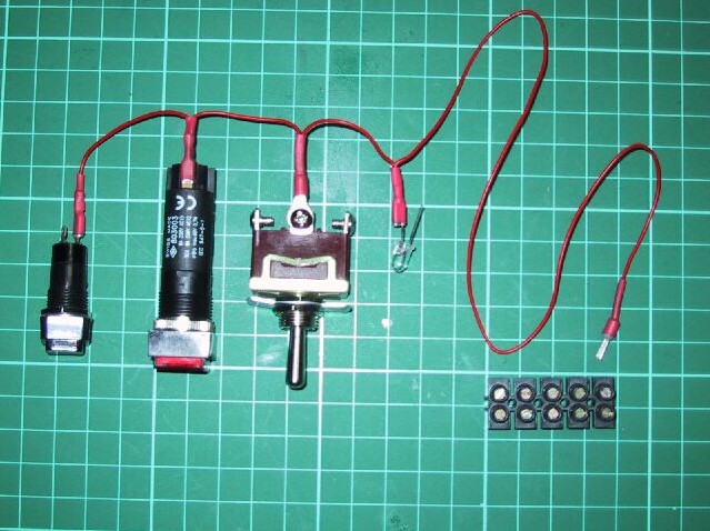
The same way the positive wire-connectors can be built using the flat cable. EPIC requires one positive wire for each
device you want to power, while the negative can be shared; it means that you can use a "bridge-system" with the red
cable for the negative pole.(shown in the example above)
|
Panel Connections
|
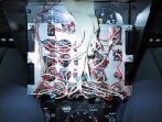
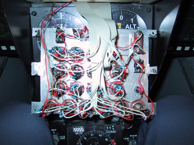
ICP Rear
|
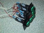
TWS Prime Rear
|
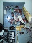
Gear Panel Rear
|
|
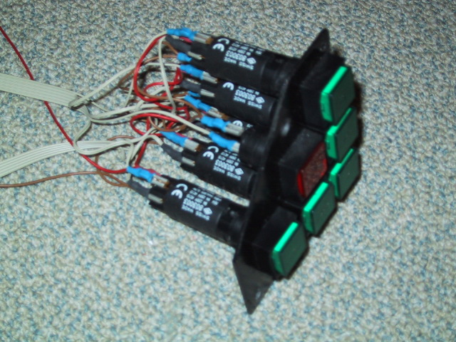
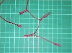
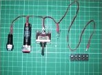
The pictures above show how the connections of different panels are done. Of course it might look complicated at the
first sight, but if you have a closer look, you will easily identify the negative wiring and the positive wires
with their connectors. The positive wiring is done using a flat cable. The other wires are those required to power
illumination of the different components.These connections follow also the same principle: one common wire
("bridge-system") for the negative pole and single wires providing the positive current.
After finishing the connections and looking at it, I also felt it looked quite complicated, but as mentioned, once you
have done it for the first time, you will cope esasily with further connections.
For those that are using the
USB system, sorry friends, but I cannot show a connection diagram, as it is reduced to
a simple plug ;)
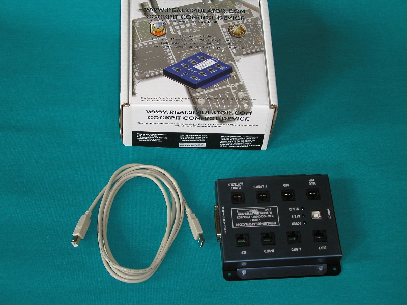
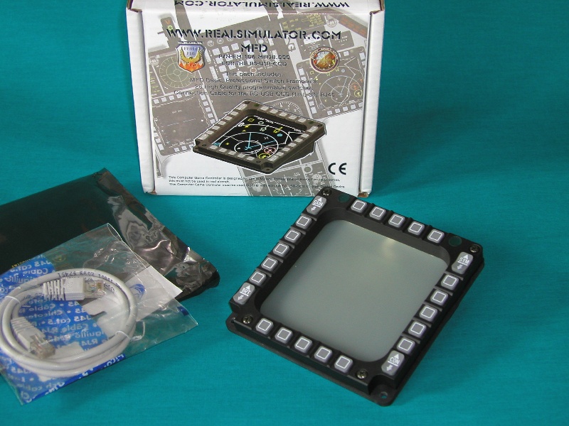
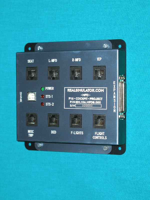
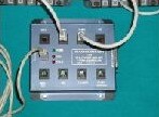
As things are getting easier, here some pictures about the USB CCD (Cockpit Control Device) and the USB MFDs. You will
see, that there is not much to explain, as the Plug & Play feature is implemented with these components. Finally no more
welding, cutting cables, checking wires, looking for short-circuits.....etc, etc. ;)
Once you have finished with the "hard work" of unwrapping the components, you can proceed making the connections.
This procedure is also "extremly complicated" and of course takes very long ;)
Let's get serious again....
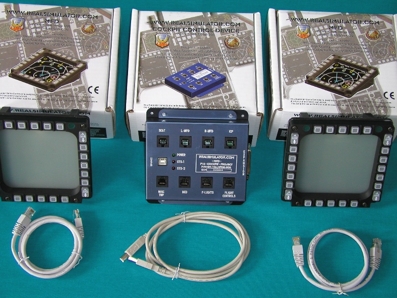
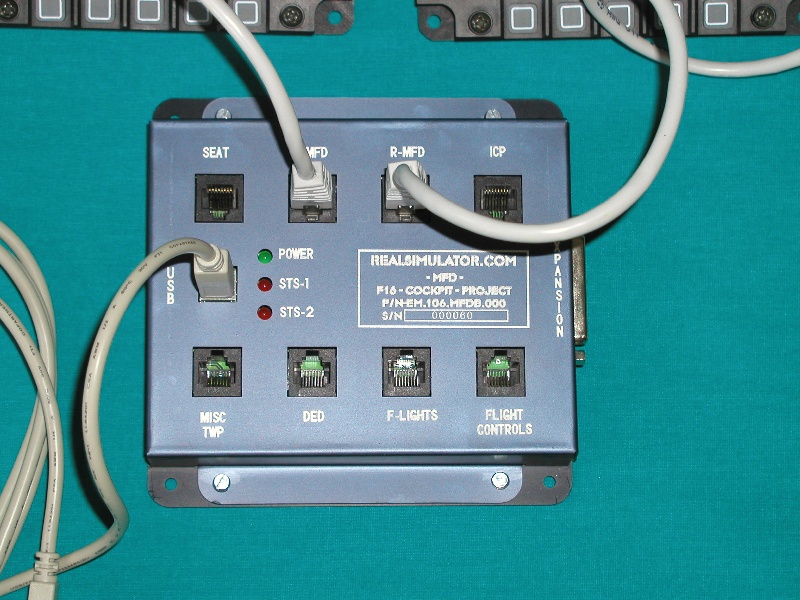
Below the pics showing the simple steps, and once you have installed the software, just connect the cable of the CCD to
an USB port. The pre-installed layout of the MFDs provides an inmediate take off in Falcon.
|
USB Connections
|
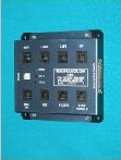
USB CCD
|
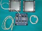
USB Set (2 x MFD, 1 CCD)
|
USB Connections
|
|
You have probably noticed, that at the right side of the CCD there is a connector, which will later host an expansion
module, allowing the powering of the complete simulator.
In brief: USB is simple to use, allows a very nice powering of the simulator, can be expanded and avoids using lots
of cables, connectors, etc.
It is the new way of powering a sim !
Note:
To zoom please select the picture with your mouse.