This section shows different materials and components which I have used to build my current simulator (Ver. 2.0)
As you will see, most of the parts can be found in regular electronic and hardware-stores, and are therefore much cheaper
than using original parts. As far as the functionality, appearence and action work as the original parts, I think it is
wise to spend less money in these components and save it for further parts of your project.
Building a simulator can soon turn out to be an expensive project, depending on the materials you use, planning the
project and finally building it.
Most of us made the same mistake: as we just wanted to sit in the sim right away, we started to build without planning
carefully. The result: we had a sim, but it did not match our own expectations. - Some parts did not look the way we would
like them to look like, the dimensions were not accurate enough, and therefore some parts did not fit, some components
looked good, but did not work propperly, etc,etc.
In other words: start all over again, spend time and money and try this time to get closer to what you have planned :(
Well here some pictures of what can be usefull for yout pit:
|
Components I
|
2 and 3 Way Switches
|
Buttons, Rockers & Switches
|
Buttons & Lights
|
|
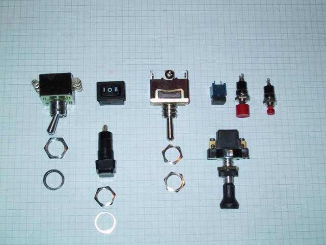
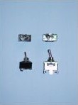
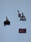
The picture on the left show switches that can be used in the pit. As you know, some of the Falcon's switches are
2-Way Switches, other 3-Way Switches. Also some of them are spring-loaded or electro-magnetical. These last two types
are very diffficult to find in a normal electronics store, but for the beginning they can be replaced with either a
2 or 3 Way Switch. Later on you can replace them, if you want a better fidelity and of course, depending on the amount
of money you want to invest.
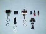
The pic at the center shows different switches and buttons that are available at normal stores.
At the upper row you can see a 2 Way Switch, a spring-loaded Rocker (on-off-on),a 3 Way Switch and three different
Push-Buttons.
The lower row shows a Push-Button (I used it for my MFDs) and a Pull/Push-Button, which can be used for example for
the Hook Switch of the Left Aux. Console of the Viper.
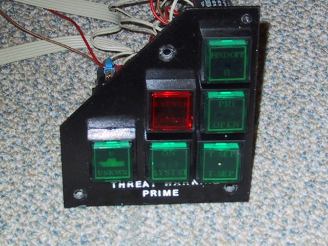
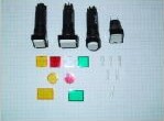
The picture at the right show the switches and buttons that I used for the ICP, the Master Caution and the TWS.
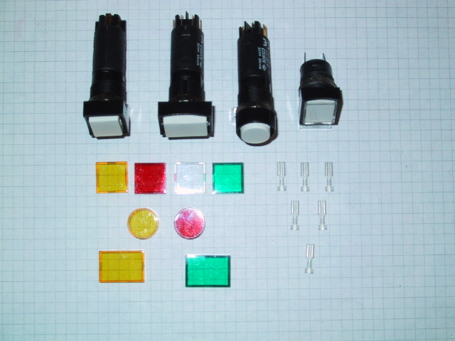
The square lights on the righ side of the pictures can be used for the Eyebrow Lights (mounted below the Glare Shield)
the EPU panel, the Electrics Panel, etc.
As you see, they are delivered with different plastic covers, white, green, yellow and red, and are therefore quite
usefull when building a cockpit. Below the transparent covers you can place a label which can easily be done with
your PC and a normal printer.
These switches are Swiss Made, and I have to say, that they are kind of expensive, but the quality is very good, they can
be eyasily be modified to function with a led instead of a bulb, and they look good. All of these switches and lights
I have, have been used for over 3 years now, and no problem appeared so far. Therefore I think they were a good
thing to invest in.
After modifying the switches, they resemble quite well the originals. Below some Pictures showing what you need for
these modifications.
|
Components II
|
Safety Covers
|
Using a LED instead of the Bulb
|

Operating Lights & Buttons
|
|
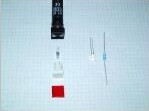
Just by using Safety Covers, which can be found in the Internet and are not expensive, a simple commercial switch becomes
a good looking military switch.
Replacing the bulb which is included in the switches by a LED is simple. Just pull the bulb out and install the LED.
You can use white, green, red or blue LEDs, which will give a neat apearence to your switch. Please remember to use also
a resistor (between 150 Ohm and 300 Ohm) before connecting your light or switch to the current. If you forget this, the
LED will burn out inmediatelly.
After installing the labels below the plastic cover, the switches are ready for use.
|
Components III
|
Warning Lights - Front
|
Warning Lights - Rear
|

Warning Light Panel
|
|
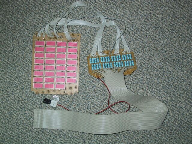
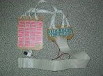
The warning Light Panel, which is located on the Right Aux. Console requires some other type of LEDs, which can also
be found at any electronics store. Wiring these LEDs is kind of tricky and takes lots of time. The panel I have built
is too big. There should not be empty place between the different LEDs. Well I found this out a long time after having
built this panel. On the next version I will keep the right dimensions ;)
Yes, it took some time to do make the connections, and it allmost drove me nuts!!! :( - Finally after finishing the
Warning Light Panel I noticed that I made a mistake: I wired the LEDs wrong. Where the positive should go I had
placed the negative. As a result I had to start all over again and build a new panel. It took again a lot of time
and nerves.:(
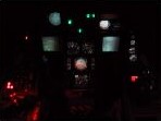
Finally it worked, and after installing a red and a blue filter on top of the panel (to make it look allmost black) the
result was ok....only the size is not correct, but that mistake will not be done on my next Sim Version.
On the pic at the right you can see how the panel remains black where the LEDs are not glowing. The labeling of each
LED was made using my PC and the printer.
|
Components IV
|
Neon Light - off
|
Neon Light - on
|
Backlit MFDs
|
|
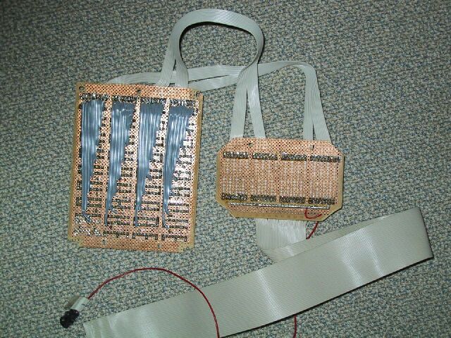
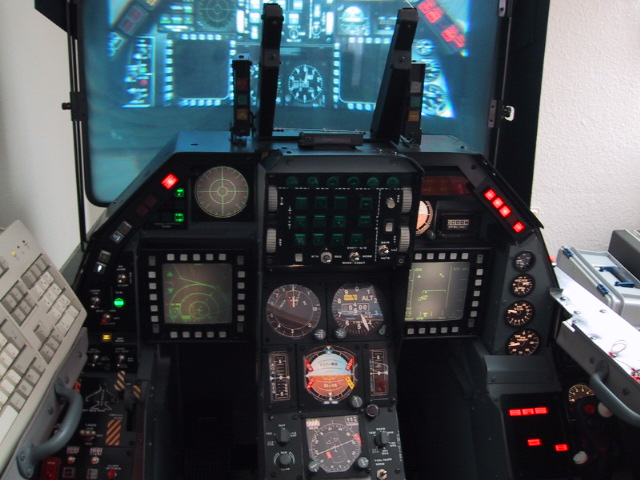
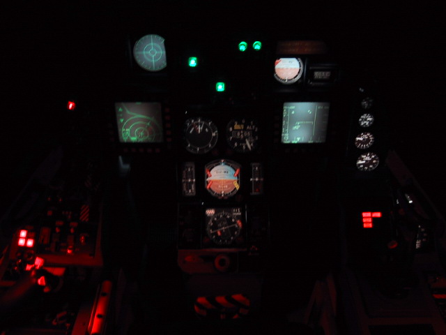
To have the analog instruments (HSI, Fuel Flow, Nozzle Position, etc) and the MFDs backlit was something that I felt was
a MUST. When flying in the dark, some instruments have to be illuminated, even if for now they were fakes. Just for
the total appearence of the sim this was important.
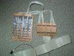
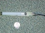
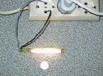
The problem was to find a light-source that could deliver good brightness but still remain as cold as possible. Neon
tubes usually work quite fine, but I had to find the propper size to be used in the sim. Another problem was that Neon
tubes normally use standard current, it means 110 V AC or even 220V AC (in Europe).
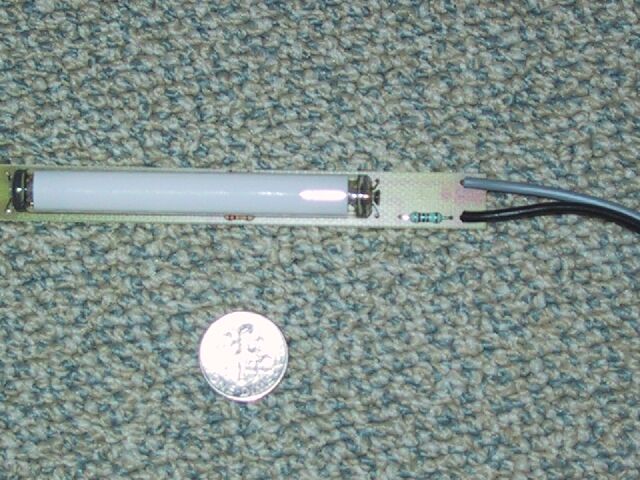
After looking around I finally could find small tubes that would fit in the casing of the MFDs and the instruments.
The size can be seen at the pictures. As a reference I placed a Dime below it.
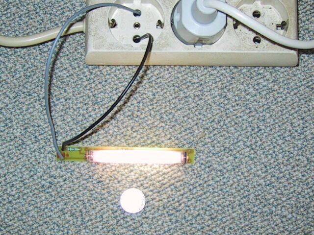
Allthough the size was ok, they still use 220 V AC and therefore I had to install a complete wire-system to power them.
I used standard cable and made sure all contacts were perfectly covered with an isolating material. Hot glue turned out
to be a good solution. You can cover all the connections with it, making sure you do not have a short circuit later on.
Note:
To zoom please select the picture with your mouse.