Powering a simulator in a way that all, or at least allmost all switches, buttons, lights, instruments, displays, etc.
requires an adecuate electronic system and interface.
Of course there are several different ways to achieve this, but it allways means lots of wiring, welding, writing the
software and other problems that require a solution.
When I started with my first simulator, I used the hardware I could find in any electronics shop, as the "MFDs" from
Quickshot. Well, that was at that time a solution to have some of the required functions to be placed inside the pit
and getting rid (partially) of using a mouse or a keyboard. As the simulations were enhanced and more functions were
activated, this first method was not enough.:(
It took some time (and lots of talking with "Pegasus") before I decided to start what I called "The EPIC Adventure", as
my knowledges about electronics were allmost nill. Even welding was unknown to me, not to talking about programming.
- Right now, after having learned a lot and after driving "Pegasus" allmost crazy, I use EPIC in my sim and would NOT
like to miss it any longer. (This of course, until something appears, that is capable of replacing what I have right
now) ;)
The EPIC delivers what you expect....but....it is not as cheap as you would like it to be, and once you have received
your Interface card and have a look at the included manual, you might start to feel that it was a wrong desicion. The
manual is written in a way that supposes that the user has knowledges about programming and electronics, and therefore
it is complicated to understand. If I had not have the helping hand of Martin "Pegasus", I am not sure, that I could
have been able to install the interface correctly and to have the program written in the right way. I must admit, that
the EPIC was just placed in a shelf for some 6 weeks, before I started to work with it. I just was afraid to fail ;)
I do not want to awake the feeling, that only the "Gurus" are capable of using EPIC propperly, as once you have had some
initial help, it works and you will be able to understand how it is done.
So my suggestion would be, not to be afraid about getting into EPIC, but make sure, that there is somebody around, who is
allready using EPIC and that is willing to help you. This way you will certainly enjoy this interface and of course,
your Sim. By the way, doubts about if you have made the right desition vanish as well. ;)
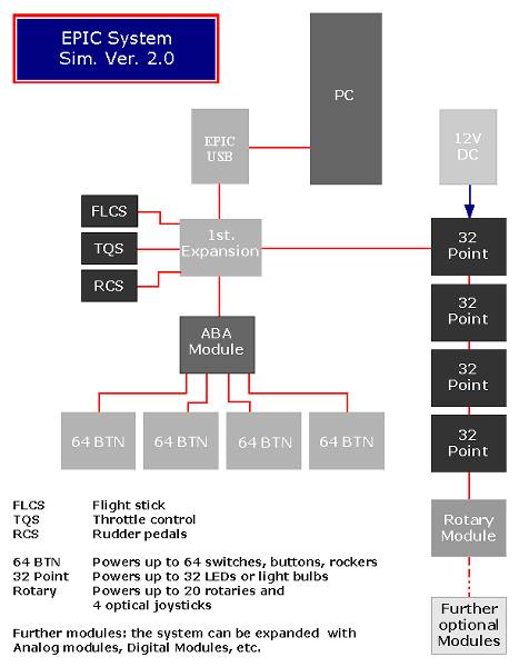
One of the advantages of the EPIC is, that you can upgrade your system accordingly to the needs of your simulator.
As a basic configuration I would recommend the following parts:
1 EPIC (ISA or USB)
1 ABA Module
1 Expansion Module
2 64 BTN Modules
If you are using ThrustMaster F-16, F-22 and TQS you need an Modification Kit for the FLCS and the TQS.
Using this basic config. you have all buttons, rockers and potis active on your HOTAS. Also up to 64 buttons,
switches or rockers can be activated.- Normally this is a good start, however I am sure, that it will not take too
long before you enlarge your system by some other components.
At this time my EPIC sytem is configured as follows:
1 EPIC (ISA).......................basic connection
1 ABA Module.....................permits the connection of further components
1 Expansion Module.............hosts the connections for HOTAS (FLCS,TQS and RCS) and the Rotary module
4 64 BTN Modules...............allowing the powering of up to 256 buttons, switches, rockers, leavers, etc
4 32 Point Modules..............activation of up to 128 LED or other lights
1 Rotary Module..................powers the function of potis (for example the 4 wheels of the ICP)
1 Modification Kit for FLCS
1 Modification Kit for TQS
|
Sim. Ver.2.0 - Electronics
|
|
|
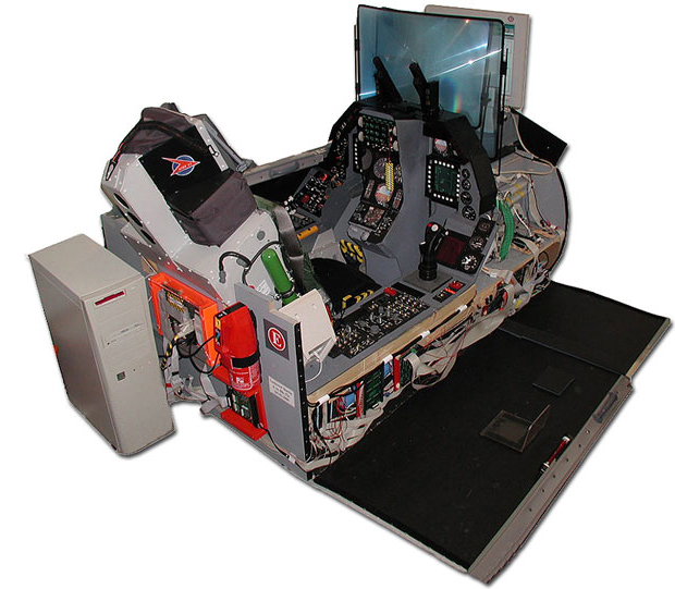
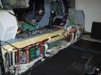
In the picture of my Ver.2.0 you can have a look on how the different electronic components were attached to the
shell. Lots of flat cable has been used to wire the lights, switches, buttons, leavers and wheels of the sim. - I
once measured them, and beleave it or not, the total lenght of cables comes up to 3200 meters !!! (1.95 miles)
When building and installing all these wires, be careful allways to know what wire is going where, as sooner or later
some maintenance has to be done, and if you do not elaborate your own wiring-plan, it might be really difficult to
find a malfunction.
I recommend, that each flat cable is interrupted 2 to 3 times using connectors. This way you can allways tell in
which section of the installation a malfunction is located. It takes some more connectors and of course some little
more money to do this, but beleave me...it is really worth it. Time is money - right? ;)
|
Components, Wires & Circuits
|
Right Side Console
|
64 BTN Module
|
ABA, Expansion and Rotary Module
|
|
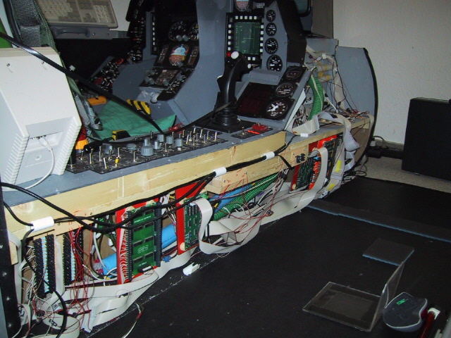
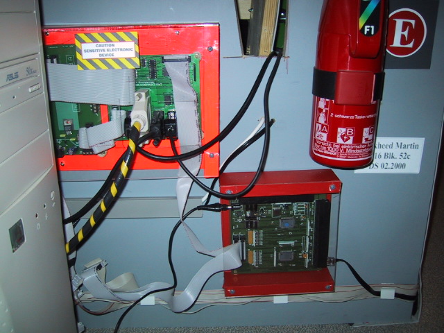
Having a look into the inside of the Right Side Console, you can observe that below the cover I have installed different
EPIC modules. - From left to right:
Resistor-Rack (this module is home-built)
64 BTN Module
32 Point Module
32 Point Module
64 BTN Module
Resistor-Rack
The same configuration was used in the Left Side Console.
This distribution gives me short distances between the components I want to connect and the powering modules. Also it
is easier to follow the wires when doing some maintenance.
The so called "Resistor-Racks" which I built are used to power down the current-delivery from the EPIC to the LEDs
I am using. As EPIC delivers 12V DC, you cannot connect the LEDs directly, as they would burn out inmediatelly. After
some experimenting I found out that using a 300 Ohm resistor works pretty well.
The green hose that comes from the Right Aux.Console is used to deliver cold air from a fan-system installed at the
front-rack of the sim. By using 3 different fans I can deliver low / high stream of cold air into the pit - that is my
Air-Conditioning System - ;) In order to avoid "piston-breathing" when using an oxygen-mask, a third fan delivers
cold air to the mask-connector. Using the A/C-selector at the right console (A/C Panel) I can power 1, 2 or 3 fans in any
combination. - Sometimes it can get really hot inside a sim. -
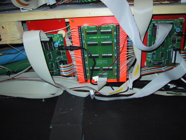
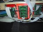
The center pic shows some detail of one of the 64 BTN modules and how the wires are attached. At each side 32 outputs and
at the top of the module 2 "hot" wires (red) which are providing the electricity.
At the left and at the right of the 63 BTN you can see the 32 Point Modules, which deliver power to the LEDs. Also note
that the flat cable has two connectors and each end of the cable has a color tape (yellow). Every flat cable that is
interrupted has it's own color-coding, allowing a fast and sure reconnection when doing maintenance.
Some of the modules are delivered vith multi-color flat cables. They look interesting, but I rather prefer to use just
grey cables and red wires. This allows a faster identification of the "hot wires".
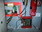
The pic on the right shows a casing that I have built to hold the ABA Module, the First Expansion Module and the
Rotary Module. This way I can connect the HOTAS without problems and centralize the electronics at one point that
is easy to access.
Note:
To zoom please select the picture with your mouse.